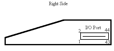
Side (Peripheral) Port Pinouts


#   Name    I/O  Use
-   ----    ---  -----------
1   VCC          +5 Volts power supply
2   SBE     >    Low if addr in >9000-94xx (sound port)
3   RESET*  >    System reset (active low)
4   EXTINT* <    External interrupt (active low)
5   A5      >    Address bus, bit 5
6   A10     >
7   A4      >
8   A11     >
9   DBIN    >    Active high = read memory
10  A3      >
11  A12     >
12  READY   <    Active high = memory is ready
13  LOAD*   <    Unmaskable interrupt (=> BLWP @>FFFC)
14  A8      >
15  A13     >
16  A14     >
17  A7      >
18  A9      >
19  A15     >    Address bus, lsb. Also CRU output bit.
20  A2      >
21  GND
22  CRUCLK* >    Inversion of TMS9900 CRUCLOCK pin
23  GND
24  PHI3*   >    Inversion of phase 3 clock
25  GND
26  WE*     >    Write Enable (derived from TMS9900 WE* pin)
27  GND
28  MBE*    >    Active low if addr in >4000-5FFF (card ROMs)
29  A6      >
30  A1      >
31  A0      >    Address bus, bit 0 (most significant)
32  MEMEN*  >    Memory access enable (active low)
33  CRUIN   <    CRU input bit to TMS9900
34  D7      <>   Data bus, bit 7 (least significant)
35  D4      <>
36  D6      <>
37  D0      <>   Data bus, bit 0 (most significant)
38  D5      <>
39  D2      <>
40  D1      <>
41  IAQ     >    Interrupt acknowledged by TMS9900
42  D3      <>
43  VDD          -5 Volts power supply
44  AUDIOIN <    To sound generator AUDIO IN pin


Keyboard connector: (inside the console) Red wire is #15
===================
pin|	12	13	14	15	9	8	6
---+-------------------------------------------------------------
5  |	=	.	,	M	N	/
4  |  space	L	K	J	H	;
1  |  enter	O	I	U	Y	P
2  |		9	8	7	6	0
7  |  fctn	2	3	4	5	1	lock
3  |  shift	S	D	F	G	A
10 |  ctrl	W	E	R	T	Q
11 |		X	C	V	B	Z

Note: pressing a key closes the contact between corresponding row + column.
Since there are no diodes to prevent current going backwards, pressing 3
keys at a time often results in appearance of a "phantom" key at the 4th
corner of the square formed by these keys (e.g 8+7+3=phantom 4: current goes
pin15-7-8-3-pin7 as if 4 were pressed)