Making your
own TI-99/4A Video Cable
.
Now that you have that
old TI up and
running, you might wish to connect it directly to a television monitor
without the use of the RF modulator. The problem has been
finding the proper video cable to make this happen. Well fret
no more, I have put together the instructions on how to make one
yourself! It is very easy and all you need are a few tools
and parts. So If you are ready, Lets go!
PARTS
LIST:
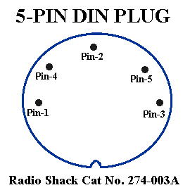
5-Pin DIN Plug (Radio Shack Cat
No. 274-003A)
Set of RCA type connectors (one for video and one for audio)
Solder (use a fine electronics grade solder, NOT the plumbers type)
Soldering iron (30W seems to work well for me)
Wire strippers
Diagonal cutting pliers
Ohm Meter (for testing the cable)
Some type of clamping device (to hold the plug still while you solder
it)
WHAT
TO DO:
1.
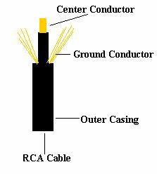
Cut the RCA connectors off of one end of the RCA cable. This
will expose the wires for us to work with and leave a set of RCA
connectors on the opposite end.
2. Strip 1/2 inch of the outer casing away, exposing the center
conductor surrounded by the grounding conductors.
3. Cut away about half of the grounding conductors so as to decrease
their quantity and enable us to fit them in the DIN plug.
4. Strip away about 1/4 inch of the insulation on the center
conductor.
5. Repeat steps 2 to 4 on the other cable.
6. Tin the center conductors of both cables (apply a thin covering of
solder to the. This will make it easier to join the conductors to the
plug.
7. Twist the ground wires from both cables together and tin them
also.
8. You should have three wires to work with, a ground and two center
conductors.
9. Cut the tips of all the wires to make a clean and even
connection. |
 |
CONNECTING THE WIRES:
You
must use caution when applying heat to the pins as the plastic holding
the pin will melt if it gets too hot.
1. Apply a small amount of
solder to the inside of pins 2, 3, and 4.
2. Heat pin-3 until the solder melts and insert one of the center
conductors, remove the soldering iron and allow to cool.
3. Repeat step 2 for pin 4
4. When connecting to pin 2, you will use the ground wire not the
center conductor
Pin-1:
Unused
Pin-2: Ground Connection
Pin-3: Audio Connection
Pin-4: Video Connection
Pin-5: Unused |
 |
TESTING
THE CONNECTIONS:
1. Use an Ohm meter to test the
continuity between the pin and the other end of the cable. If you do
not get a reading, then one of the connections is bad. Check the
connection and reapply solder if needed.
2. The things to check for are that you have continuity between the
grounds on both RCA cables and pin-2 and that the center conductors
have continuity from pins 3 and 4 to the respective RCA pins.
You also want to ensure that none of the pins are shorting to any other
pin.
This page was formerly
hosted at :
http://www.nwlink.com/~theraven/ti994a/dinplug.htm
It disappeared from its
original location and I am now hosting it here.
If you are the original poster and object let me know and I'll remove
it.
Home
| Site
Map |
Search
| Contact/E-mail
| Link
To The HCP | FAQ
| Newsletter
|
Privacy